Tidak ada produk di keranjang.
PLC Explained: What Is a PLC? Working Principle, Architecture & Applications
Introduction
In modern industrial automation, a PLC (Programmable Logic Controller) is one of the most critical control devices on the factory floor. Whether it’s packaging machines, conveyor systems, injection molding machines, or robotic work cells, PLCs handle real-time signal acquisition, logic execution, and output control.
Many people mistakenly think of a PLC as an “industrial computer,” but this is inaccurate.
A PLC is not merely a computer — it is a real-time controller designed specifically for deterministic machine control.
Key differences include:
- Computers focus on computational performance, and execution timing is not guaranteed.
- PLCs prioritize deterministic execution, ensuring identical timing and sequence in every scan cycle.
- A few milliseconds of delay is acceptable on a PC, but the same delay in a PLC may cause machine crashes or unsafe behavior.
Understanding how PLCs operate is the foundation of mastering industrial automation.
How a PLC Works
The PLC Scan Cycle
PLCs run control programs in a repetitive loop known as the scan cycle. Each cycle consists of three main steps:
- Input Scan
Reads the states of sensors, switches, and analog values, and stores them in input memory. - Program Execution
Executes logic instructions (Ladder, Function Blocks, Structured Text) based on input memory and internal states. - Output Update
Writes calculated results to physical outputs such as relays, solenoid valves, contactors, or drive commands.
A complete loop is called one scan cycle. Typical scan times range from 1–10 ms, depending on CPU performance and program size.
Real-Time and Deterministic Control
The defining characteristic of a PLC is determinism:
- The same logic
- Runs in the same order
- At predictable time intervals
This deterministic behavior is what separates a PLC from a PC.
| Feature | PLC | PC |
|---|---|---|
| Execution timing | Fixed scan cycle | Non-deterministic |
| Reliability | High | Moderate |
| Timing precision | Milliseconds | Unpredictable |
| Usage | Machine control | HMI, computing, general tasks |
Real-time determinism ensures safe and consistent machine operation.
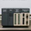
PLC Hardware Architecture
A PLC typically includes several essential hardware components:
CPU
The core processor responsible for:
- Program execution
- Internal memory management
- Scan cycle control
- Diagnostics
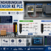
Input Modules (DI / AI)
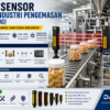
DI (Digital Inputs): Read ON/OFF signals such as sensors, switches, and limit switches.
AI (Analog Inputs): Read continuous values (e.g., 4–20 mA, 0–10 V) from pressure, temperature, or flow sensors.
Output Modules (DO / AO)
DO (Digital Outputs): Drive relays, solenoid valves, or motor starters.
AO (Analog Outputs): Provide control signals to VFDs or servo amplifiers.
Communication Modules
Support industrial protocols such as:
- Modbus RTU / TCP
- Profinet / Profibus
- EtherNet/IP
- CANopen
- MQTT (for IIoT applications)
PLC Memory Areas
Common memory sections include:
- I/Q area: Input/Output image registers
- M area: Internal relays (markers)
- D/DB: Data registers or data blocks
- Timers & Counters: T/C resources for time-based logic
Power Supply and Noise Immunity
Industrial PLCs feature:
- 24V DC industrial-grade power supply
- Surge protection
- Optical isolation on IO channels
- Metal shielding against EMI
- Robust grounding design
PLC Control Logic
PLC programming primarily uses graphical and structured languages:
Ladder Diagram (LD)
Simulates electrical relay logic using:
- Normally Open (NO) contacts
- Normally Closed (NC) contacts
- Coils (outputs)
- Timers
- Counters
It is intuitive for electricians and automation engineers.
Function Block Diagram (FBD)
Used for:
- Process control
- Analog signal processing
- PID control
Structured Text (ST)
A high-level language combining elements of C and Pascal:
IF Sensor = TRUE THEN
    Motor := TRUE;
END_IF;
Suitable for complex algorithms.
Industrial Application Examples
Conveyor System Control
Typical logic flow:
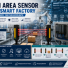
- Photo sensor detects product
- Motor starts
- Jam detection triggers alarms
- Status feedback sent to HMI or SCADA
Pneumatic Cylinder Motion Control
Basic cycle:
- Forward limit switch → trigger retract
- Retract limit switch → trigger forward
- Timeout monitoring for abnormal motion
Multi-Machine Coordination
For integrated systems such as a machining center with robots and conveyors:
- Upstream machine sends “cycle complete”
- Downstream machine sends “ready” status
- Synchronization via fieldbus communication
Key Parameters When Selecting or Designing with PLCs
IO Count
Number of digital and analog input/output points.
Scan Time
Lower scan time = faster response and better control precision.
Memory Capacity
Affects program size, data logging, and buffer storage.
Expansion Capability
Important for scalable systems:
- Expansion IO racks
- Communication cards
- High-speed counters
- Motion modules
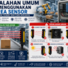
Common Engineering Issues
Input Signal Bounce (I/O Chattering)
Causes:
- Mechanical switch bounce
- Electrical interference
- Poor wiring
Solutions:
- Software debouncing
- Hardware filters
- Use of industrial-grade sensors
Noise Interference
Typically caused by:
- VFDs
- Servo motors
- Welding machines
Solutions:
- Shielded cables
- Cable routing separation
- Grounding optimization
Communication Failure
Causes:
- IP address conflicts
- Damaged cables
- Mismatched communication settings
- Incorrect baud rate or protocol
Best Practices (Essential for Engineers)
IO Zoning and Management
Separate IO according to:
- Safety
- Motion control
- Process logic
- Remote IO
Modular Programming
Divide logic into reusable modules:
- Motor control
- Cylinder control
- Alarm management
- Communication modules
- Data processing
Improves readability and maintenance.
Program Comments & Version Control
In real engineering, 80% of work is troubleshooting systems written by others.
Recommendations:
- Add clear comments to key logic
- Maintain version history
- Use Git/SVN or vendor-provided version tools
- Keep a “factory default version” for safety
FAQ
Q1: What is the difference between a PLC and a microcontroller?
PLCs are industrial-grade, highly reliable, easy to program, and designed for harsh environments.
Microcontrollers are cost-effective but require longer development time.
Q2: Can a PLC replace an industrial PC?
No. PLCs handle machine control, while IPCs handle interfaces, computing, and data processing.
Q3: Why do PLCs use scan cycles?
To guarantee deterministic execution — crucial for safe machine operation.
Q4: Which programming language is best for beginners?
Ladder Diagram is the easiest and most intuitive.
Conclusion
- A PLC is fundamentally a real-time deterministic controller for industrial machines.
- It operates using a structured scan cycle: input → logic → output.
- PLC hardware includes CPU, IO, communication modules, and industrial-grade isolation.
- Common languages include Ladder, FBD, and ST.
- Proper engineering practices improve system reliability and maintainability.
PLCs remain the backbone of modern industrial automation.


Tambah komentar
Anda harus masuk untuk berkomentar.